Neptuno
TELECOMMUNICATIONS
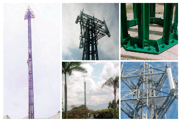
PERFILATED POLE
PERFILATED POLE
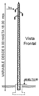
Neptuno’s Perfilated Monopole is made of steel angles bolted together and its maximum height is 45 meters (147.6 ft). It can be engineered to resist a wind speed of up to 150 Mph, and to support the same typical load of a standard monopole. However, the value-added benefits of this product are:
- Its foundation is of 1 meter by 1 meter, which reduces the space required by a traditional monopole.
- It is erected like a tower, without the need of a crane or heavy-duty equipment like in the case of a traditional monopole.
- It is easy to transport, therefore it could also be deployed in hard to reach sites.
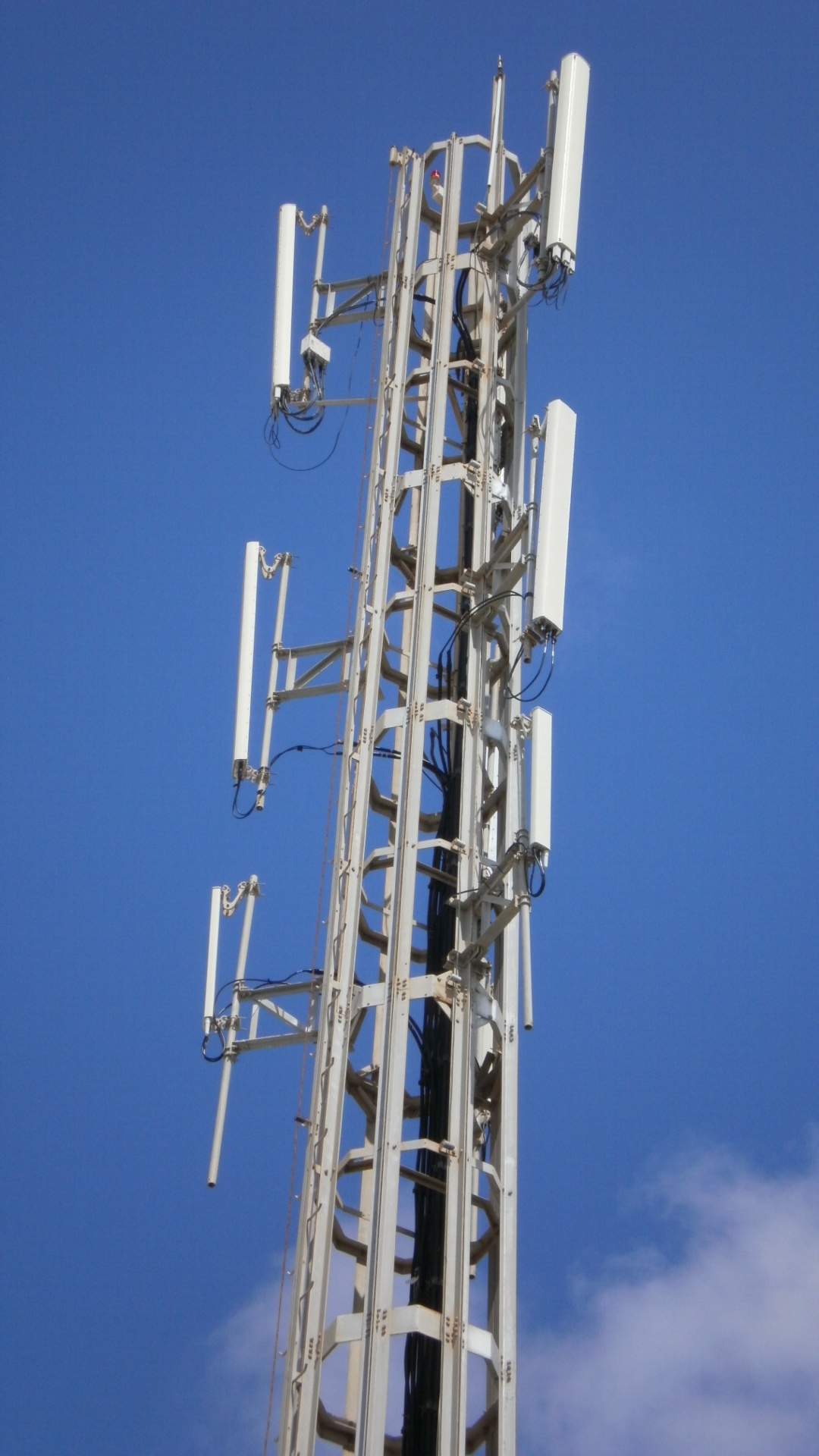
MONOPOLES POR TELECOMMUNICATIONS
MONOPOLES POR TELECOMMUNICATIONS
TYPICAL LOADS
- Nine (9) Cellular Antennas KATHREIN or Similar.
- Two (2) Microwave Antennas Ø 4 ft (1,20 mts) at 13 ft (4 mts) of the top.
- Two (2) Microwave Antennas Ø 4 ft (1,20 mts) at 33 ft (10 mts) of the ground.
ESPECIFICATIONS
According to U.S.A.- EIA-222F Standards
- Section: Octagonal
- Base width 26 ¾´´(680 mm), Top width 9 ½´´ (240 mm) variable depending on monopole height.
- They come in various length sections of approximately 13 ft each (4,00 mts) .
- Up to 130 ft Height (40 Mts).
- Access Ladder. (With optional Safety Climb)
- Vertical Cable Guide Support Ladder.
- Cellular and microwave antennas Supports.
- Ground Connections.
- Complete with Hot Dip Galvanized A 325 Bolts, Nuts and Washers.
- All Materials Made using Structural Steel A 36 Standard.
- All Materials Hot Dip Galvanized according to ASTM- 123 A.
- Typical Design Parameters:
- Design Wind Speed: 74,5 Mph (120 Km/hour) *
- Maximum Flexion and Torsion Parameters: +- 1º
- * According to Clients Specifications
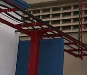
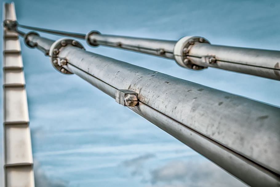
Support Poles
Support Poles for Wave Guides
MODEL N-1000
|
||||||||||||||||||||||||||
|
||||||||||||||||||||||||||
Standard Wave Guide Ladder
Standard Wave Guide Ladder.
MODEL N-3000
| MODEL | A | B | MODEL | A | B |
| N-3001 | 6000 | 400 | N-3005 | 3000 | 400 |
| N-3002 | 6000 | 600 | N-3006 | 3000 | 600 |
| N-3003 | 6000 | 800 | N-3007 | 3000 | 800 |
| N-3004 | 6000 | 1000 | N-3008 | 3000 | 1000 |
Support Poles for Wave Guides
Support Poles for Wave Guides
MODEL N – 4000
| MODEL | A | B | C | D |
| N-4001 | 250 | 420 | 400 | |
| N-4002 | 250 | 620 | 400 | |
| N-4003 | 250 | 820 | 400 | |
| N-4004 | 250 | 1020 | 400 |
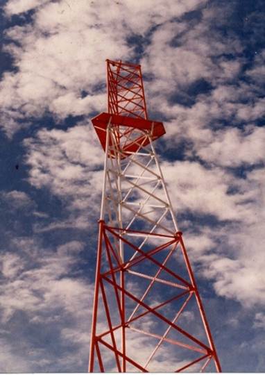
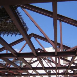
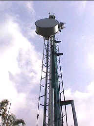
Self supported towers
Self supported towers
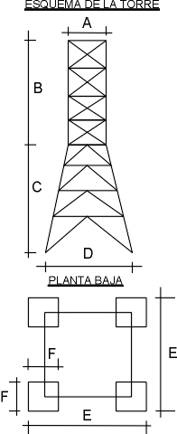
Self supported towers
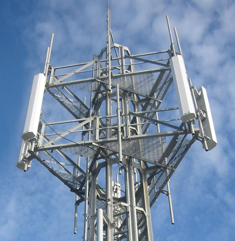
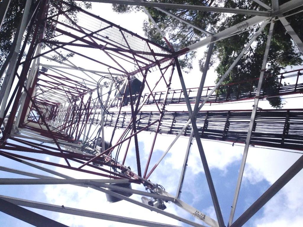
Self supported towers are more rigid towers and less sensible to torsion. This is the reason of why they are used to support several antennas of great surface and work at high frequencies (2 GHz. and more).
They are usually used when the floor surface does not allow brace fixtures (accidental terrain, urban zone with exiguous terrain). It’s section may be square or triangular.
It’s lower part is pyramidal and the upper part continues as a constant section armour.
The width of it’s base is related to it’s height.
The effort area is the sum of the parabolic antenna’s areas to be installed (in the worst of the cases).
|
|||||||||||||||||||||||||||||||||||||||||||||||||||||||||||||||||||||||||||||||||||||||||||||||||||||||||||||||||||||||||||||||||||||||||||||||||||||||||
|
|||||||||||||||||||||||||||||||||||||||||||||||||||||||||||||||||||||||||||||||||||||||||||||||||||||||||||||||||||||||||||||||||||||||||||||||||||||||||||||||||||||||||||||||||||||||||||||||||||||||||||||||||||||||||||||||||||||||||||||||||||||||||||||||||||||||||||||||||
Fastening Accesories
Fastening Accesories
MODEL N-5000
| MODEL | DESCRIPTION |
| N-5001 | Joint Angles |
| N-5002 | Continued thread screws |
| N-5003 | Joint Screws |
| N-5004 | Joint Angles |
SOIL SYSTEM
SOIL SYSTEM
MODEL N-6000
| MODEL | DESCRIPTION |
| N-6001 | Uncovered cooper cable 2/00 |
| N-6002 | Copperweld Soil Bar |
| N-6003 | Copperweld Bar Connectors |
| N-6004 | Tower Connector |
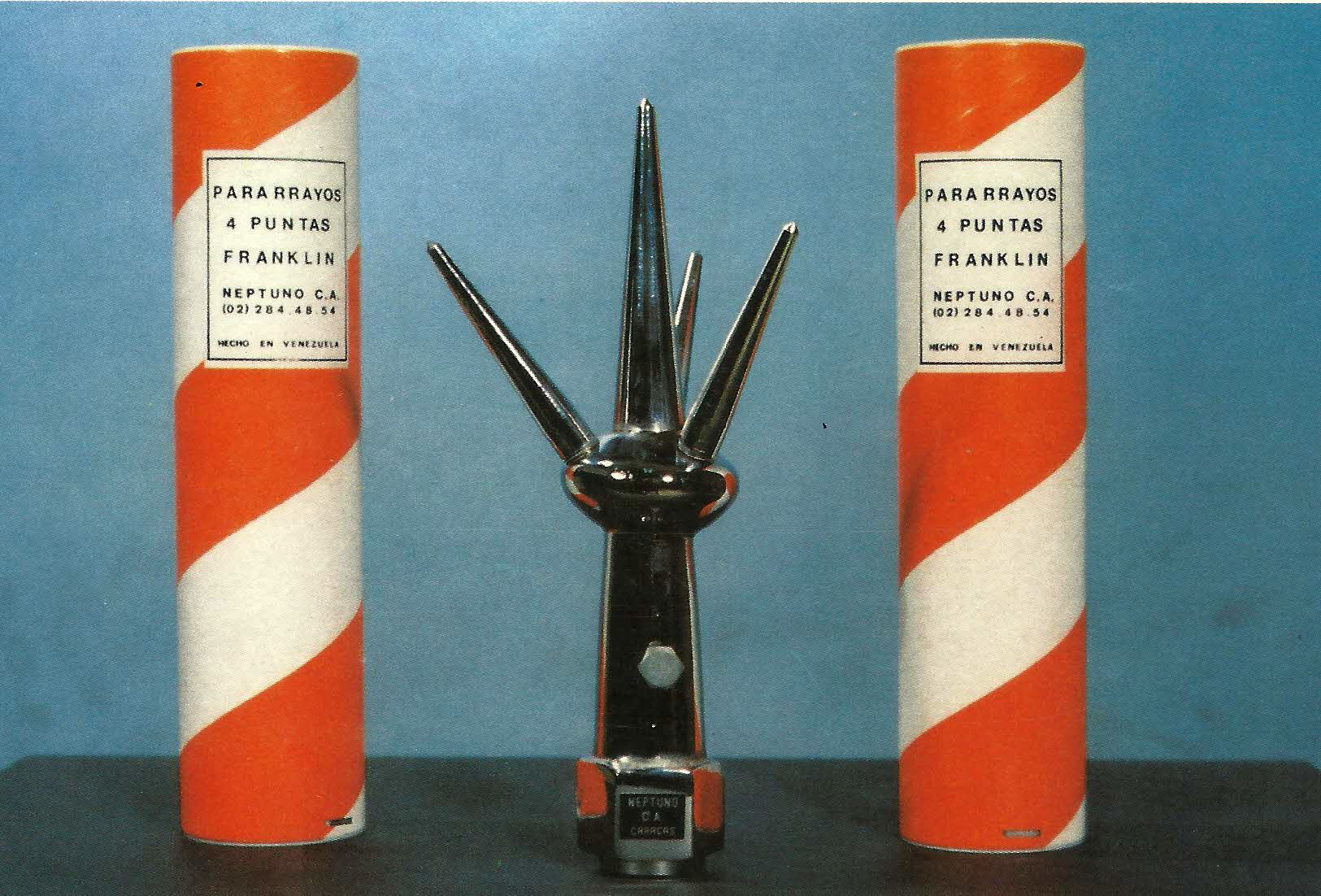
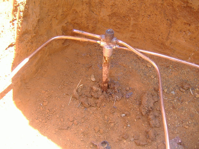
POINT FRANKLIN LIGHTNING CONDUCTOR
POINT FRANKLIN LIGHTNING CONDUCTOR
FUNCTIONALITY
The point Franklin lightning conductor is a protection element. It’s function is to capture lightnings (atmospheric discharges) and transfer it’s energy to earth in a safe way without affecting the protected structure.
APLICATIONS
On communication towers, buildings, houses, factories, hangars and any other edification and for construction subject to atmospheric discharges.
CONNECTION
For an effective ground connection, it is made through 2 screws that join correctly the inside of the lightning conductor it is recommended the use of uncovered copper wire Nº 2/0 or 3/0 (of 19 threads).
WEIGHT
Approximately 1.5 Kilograms.
FIXTURE
Comes to be screwed directly to a ¾” conductor tube properly fixed.
| MODEL | DESCRIPTION |
| N-8001 | Franklin Point |
| N-8002 | Uncovered cooper cable Nº 2/0 |
| N-8003 | Fixation angles to towers |
| N-8004 | Copperweld Bar |
| N-8005 | Ground connector |
| N-8006 | Fixture piece of the lightning conductor to tower |
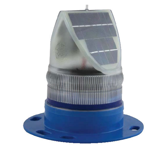
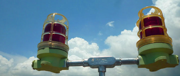
BEACON BEAMS
BEACON BEAMS
Positioning of Obstacle Lights: One or more lights must be positioned on top of the obstacle. If the upper part of the obstacle is more than 45 meters above the ground level, additional lights must be positioned at intermediate levels.
Emplazamiento de luz de Obstáculos
Se coloca una o más luces en la parte superior de obstáculos. Si la parte superior del obstáculo se encuentra a más de cuarenta y cinco (45) metros sobre el nivel del terreno circundante, se colocarán luces adicionales a niveles intermedios.
The number and positioning of the lights at any level of the sorrounding terrain must be such so that the obstacle is indicated on all azimuths. The upper light or lights must be positioned so that it shows the border or upper point of the obstacle. If the obstale is to be a chimeney the lights must be positioned between 1,50 meters and 3.00 meters below the peak. In case the obstacles are of great exterior or very closely grouped, lights must be positioned at the most upper point relative to the signaling surface, at interval not greater than 45 meters so as to indicate it’s general configuration and the size of the obstacle.

|
MODEL
|
DESCRIPTION
|
| N-11001 | Double Obtruction Lamp |
| N-11002 | Transfer Relay |
| N-11003 | Photoelectric Cell |
| N-11004 | Photoelectric Cell Base |
| N-11009 | LONG LIFE LIGTH BULBS |
| O-11011 | Single Obstruction Lamp |
100%496″ cellspacing=”0″ cellpadding=”5″ bgcolor=”#ffffff”>
BEACOM BEAM SYSTEM FOR TOWERS
OF UP TO 45 MTS
MODEL N-9000MODELDESCRIPTIONQUANTITYN-9001Double Obstruction Lamp1N-9002Transfer Relay1N-9003Photoelectric Cell1N-9004Photoelectric Cell Base1N-9005Condulet L Box1N-9006Conduit Tube 1″
N-9007TW Nº 14 Cable
N-9008Long Life Light Bulbs2N-9009Fixation Angles for Conduit Tube
|
||||||||||||||||||||||||||||||||||||||
INDIVIDUAL ACCESORIES FOR OBSTRUCTION LIGHT
INDIVIDUAL ACCESORIES FOR OBSTRUCTION LIGHT
|
MODELO N-11000
|
|
| MODEL | DESCRIPTION |
| N-11001 | Double Obstruction Lamp Type G.E. |
| N-11002 | Transfer Relay |
| N-11003 | Photoelectric Cell |
| N-11004 | Photoelectric Cell Base |
| N-11005 | Conduit Tube 1″ |
| N-11006 | TW Nº 14 Cable |
| N-11007 | Condulet L Box |
| N-11008 | Condulet X Box |
| N-11009 | Long Life Light Bulbs |
| N-11010 | Flash Beacon |
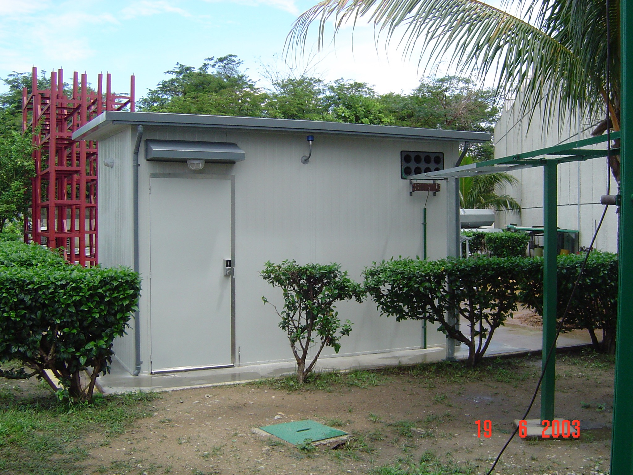
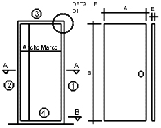
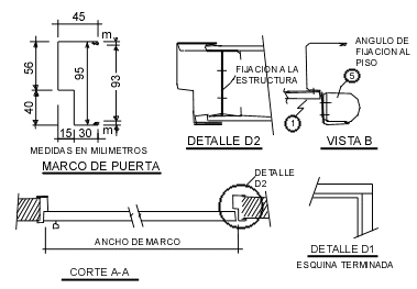
PREFABRICATED SHELTERS
CASETAS PREFABRICADAS
The offered NEPTUNO Shelter is completely prefabricated and presents the folowing:
- Solid construction
- Durable through time
- High degree of thermic isolation and easy to mount.
WALLS:
They are of 70mm “Sandwich” type. Their faces are made of galvanized steel plates with longitudinal reinforcements wich give them the necessary resistance, it’s center is made of expanded poliurethane wich fills the space between plates. The exterior walls are covered with a plastic piece whose components of resine and quartz give them an exceptional resistance to exterior agents providing low maintenance. An aluminum skirting board. The vertical and upper angles are finished in a decorative element that keep the electric conductors. The walls are formed by panels that fit perfectly making a water proof joint.
FLOOR:
Carpet or vinyl cover be used.
BASE:
The prefabricated unit includes the resting ground which is made of the same elements as the walls and on top of which the shelter tube structure is placed. This ground is placed on top of a steel tube structure, placed directly on the terrain so no foundations are required.
IRESTROOM:
It is modular type. Has a complete plumbing system installed so only the sanitary equipment is needed.
ELECTRICAL INSTALLATION:
It is made through the conductors that are placed on the wall or ceiling joints. These are decorative elements so the electrical installation can not be seen.
CEILING:
The upper section is made of a steel plate with exterior ribs, the interior is made of a plain plate and between them is the expanded poliurethane. It is formed by plates that fit perfectly between them. Anyhow a sealing element is used on the joints. It leans on top of the exterior walls and it is covered with a coat of a waterproof element completing it’s watertight characteristics. All elements are characterized by the use of poliurethane as stuffing because it has outstanding properties as a thermal insulator, good mechanic resistance, it is auto-extinguishable, it is not attacked by other substances, it does not absorb humidity so it does not rot and does not vary through time.
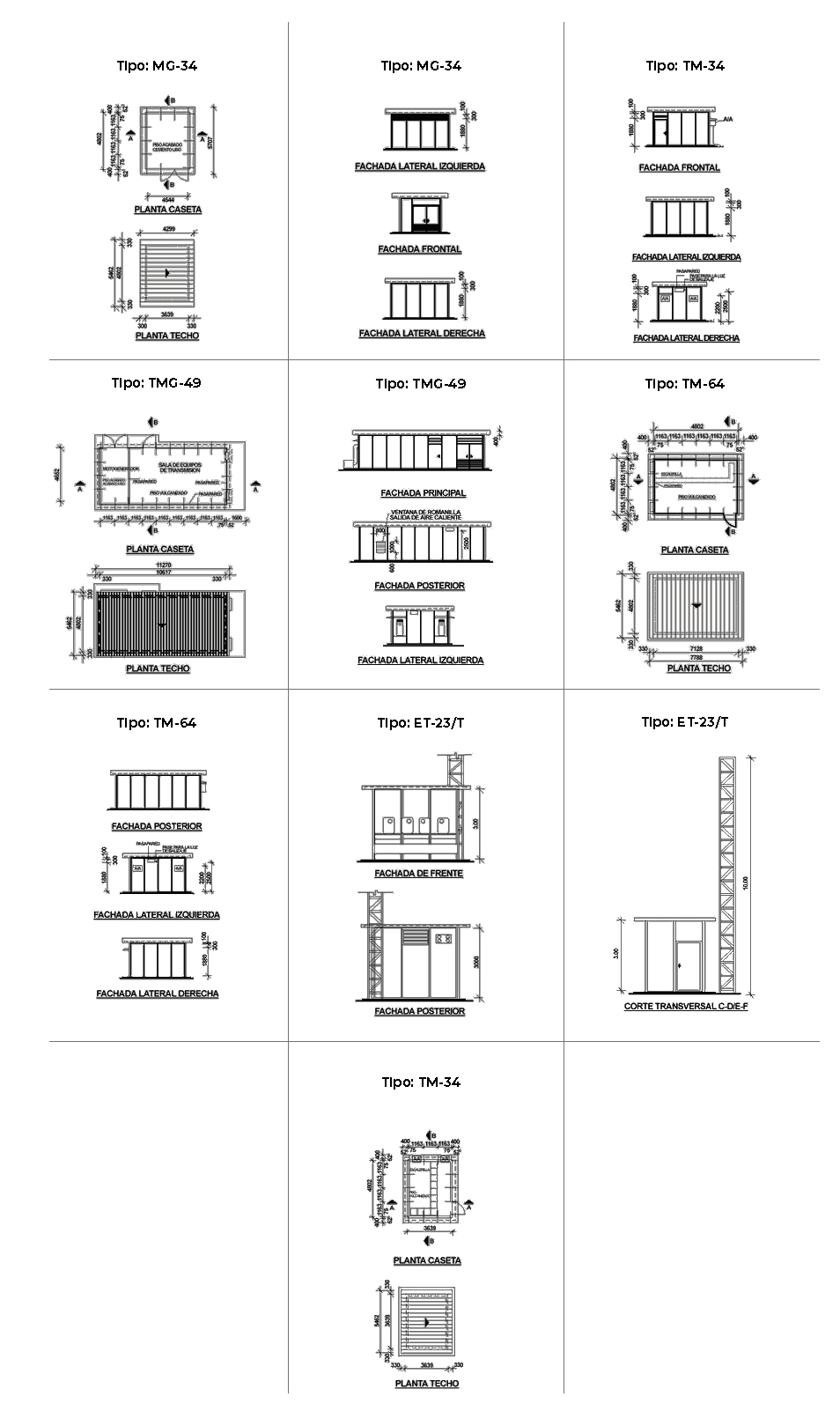
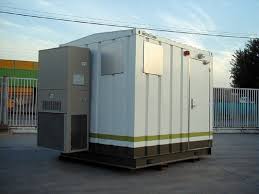
CONTAINER FOR TELECOMMUNICATION EQUIPMENT
CONTAINER FOR TELECOMMUNICATION EQUIPMENT
The NEPTUNO, C.A. container (N-19000) is designed to acommodate telephone equipment, data and/or radio communication. It’s use quickly satisfies service needs, in urban or rural areas. Among the applications we cite the following:
- On permanent or provisional installations.
- To solve emergency problems.
- For emergency developments without design harm.
- On price competitive markets
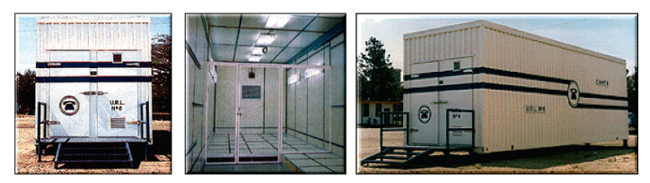
The NEPTUNO, C.A. (N-19000) container is of solid construction, practical, secure and complies with the strictest quality requirements. Because of it’s structural design and interior distribution, protects the equipment once installed. This is true for static conditions as for the transportation of the shelter to its final destination with all the equipment installed and ready to operate not needing to make any adaptations, just attaching the energy supply.
The NEPTUNO N-19000 telecom container dimensions have been
studied to allow the instalation of late digital technology equipment
along with all the required accesories.
The NEPTUNO, C.A. (N-19000) container is conceptualized to satisfy the necesities of our clients, that embraces from installation of new telephone centers, radio communication, repeating stations, supervision and control systems (SCADA) and telemetry in general to enlargements or equipment movement that have space limitations in the actual buildings. The dimensions of the NEPTUNO, C.A. (N-19000) container for telecommunication equipment has been adapted so that the latest technological digital equipment may be installed, among them. Telephone Conmutation Equipment for Autonomus Centers (“Headquarters”) or for Remote Line Units (URL).
General Characteristics:
- Construction based on metalic structures (U and I profiles, steel angles and plates).
- External dimensions and weight according to ISO-668 and 3874 requirements that guarantees transportation throughout the world.
- Ceiling and wall system based on double plate hot galvanized steel of 1/16″, with expanded poliurethane between them, wich provides an excellent thermal, acoustic and radiofrecuency isolation.
- The internal walls and ceiling are covered by a bakelite decorative plate.
- The floor is formed by a 6mm thick steel plate, finished with vinyl tiles, on top of wich a false floor can be installed, adaptable (in area and height) to the telecommunication equipment requirements.
- The container has two external doors of airtight closure, they have a special security system on the locks.
- One of the doors acceses a small room specially designed to store a bank of batteries independent of the rest of the equipment and foreseen with it’s air extractor for the posible battery fumes. The walls and floor of this room are protected with antiacid paint.
- The container internally has two very well defined areas; a partition with a door separates them. The first one has: the main distribuitor (MDF), D.C. energy system (rectifier and panel), alarms and control panels and the administration, operation and maintenance console of the center. The second one may accomodate for example, two wings for the conmunication equipment.
- The back of the container has two openings for the duct ends of the external air conditioned injection and return. The injection duct is beneath the false floor. Through screws and openings scattered for equipment an optimun distribuition of the conditioned air from a split type does not require any external installation.
- The slower structure has six metalic supports of 25 cm high on top of wich the container is placed. This is the optimum space between the container’s floor and the installation platform so that the phone and electricity cables may be installed easily. Aditionally the container’s floor has special openings for the cables. It also has two grunching sytems, one for the container’s structure and one for the telecommunication equipment.
- The container may be delivered at the desired location with all it’s equipment installed and tested, ready for its connection and final test, obtaining a great economy in costs and time, reaching great rentability of the investment and meeting the development goals.